Minor shifter update
While I’m still a ways away from driving and racing this thing, been making tweaks along the way.
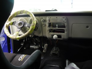
The new Hurst Competiton Plus shifter for the M21 Muncie came with its standard shift handle, which fits well and offers relatively short throws with its compact length. One thing I could tell I didn’t like though, was how far away it sits from the steering wheel-
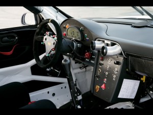
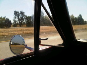
It is a ways to the right, further forward, and way below the height of the steering wheel. While there isn’t that much shifting in Solo, it is done from time to time, and having to reach that far, wasn’t something I wanted to do. A race car trend you see these days (at least in classes where steering-wheel paddle shifters are not allowed), is big tall shifters, so the driver doesn’t have to reach as far to shift, letting them keep more hands on the wheel. This Porsche is a good example:
Hurst sells several different handles for their shifter, for good fitment into all the different cars they sell shifters for – older and new musclecars, sports cars, even pickup trucks.
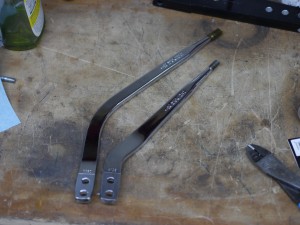
Supplied shifter stick on the right, round 2 shifter on the left. The new one places the shift knob 2″ higher up, about 1″ further back, and though it’s hard to see from the picture in this plane, about 1.5″ more to the left, closer to the driver. This is the shifter stick sold for Jeeps!
This sort of swap is a good quiet weeknight job while everyone’s asleep. Very happy with the result!
You sunk my battleship
In part 4 of Comparative Vehicle Dynamics we went through looking at the key variables contributing to lateral grip and skidpad performance. Both these things are very important in autocross, where you spend the vast majority of time at the car’s lateral limit.
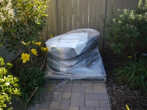 (Wheels and tires arrived on their own pallet, very nice!)
One of those key variables is track width – the wider, the less lateral weight transfer, and the more potential grip at the axle. This width ends up costing later in transitions, but my preference is still to take the wider track width, especially on a car that is somewhat under-tired compared to its competition. Especially too in the front, where the width tends to be a bit more manageable through slaloms. Especially three, in a car that has craptastic front suspension geometry, no ABS, etc.
When measuring for front wheels, most of the look-see was done at ride height, with the camber values around -1. I knew I’d run more negative for racing, but on the weird chance I ran more straight-up for the street or whatnot, wanted to be sure the wheel/tire wouldn’t be out of room outboard; a wheel too far inset can be pushed outward easily with spacers – ones too far outboard, require the use of those hard-to-find “negative displacement spacers” 😉
It looked like 5″ backspace might just barely be not enough backspace in front, and since it was easiest to step in .5″ increments, went with 5.5″ front backspacing. This was a bit of a bummer, since 5″ looked perfect (and after delivery still appears perfect) for the rear, meaning the front and rear wheels would (and do) have different dimensions.
When putting the car back on the ground for the first time in forever, I had the front suspension at its full -6 degrees camber. While the exact amount varies based on tire diameter and where you are already aligned, in general, for every one degree of negative camber you add, you move the top of the tire inboard by about .1″. So by adding over 4 degrees more negative camber from where I was when first measuring for wheels/tires, I moved the top of the tire inboard by over .4″, almost half an inch.
In the 240sx world when I owned mine, some people worked to get their wheel/tire combination pushed every last bit out to the limits inside their fenderwells. Tires so close to metal, you’d swear there’s no way they’d clear as the suspension moved, yet somehow they did. This was the pursuit of “flush stance” and those that achieved it were “hellaflush”. While this pursuit is mostly for looks, I happen to generally agree with the idea, as the further outboard you go, the more you’ve widened the track width. When done right, I think it looks good.
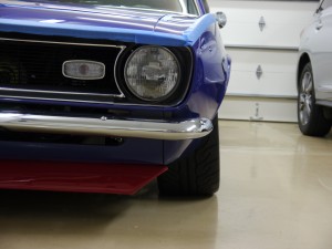
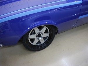
For every trend that gets branded, the opposite of the trend has to get branded too, and those that ran wheels/tires with too high an offset, or too much backspace, were said to have “sunken battleship” – because the wheel/tire appeared sunken into the wheelwell when viewed from the side. That’s how the Camaro looks with this backspacing – ugly and certainly not hellaflush!
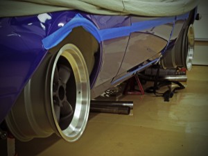
I have some wheel spacers to go buy now for sure. Won’t be able to get the wheel/tire all the way out to the outer edge as is the modern style, with this car under the ST ruleset. The wheelwell is made of metal, and there is no allowance for its modification. Just inside of the outer blue fender, the inner fender has a flat plane for 1″ or so, before it forms a bowl shape upward. You can see it somewhat here, the wheelwell on the right has its outer portion facing the camera (inner portion is not a problem):
Because of this, the front of the car would either have to be up really high (blech!) or have a bit of the sunken battleship. I believe the wheels can go outboard at least 1/2″ from the above, possibly up to 1″ per side. Based on some Photoshop pixel math, it looks like the wheels need to go outboard 1″ to have the outer portion of the tire at the ground in line vertically with the exterior fender lip.
In addition to the extra track width on the end that needs it, this has the additional benefit of allowing for a bit more steering lock before the tires start to rub the frame inboard. But most importantly it should look much much better!!!
Would have a profile shot of the whole car on the ground at this point, but it looks ridiculous, as the rear springs are about 3″ too high. Like a wonky dragster, but worse. New rear springs are on order but will take while…ugg…
Few random pictures – two sets of wheels & engine compartment
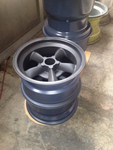
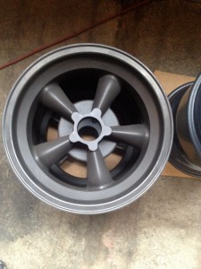
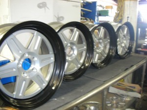
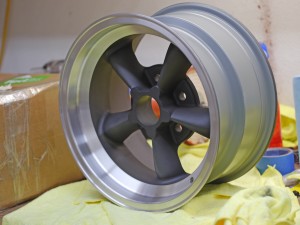
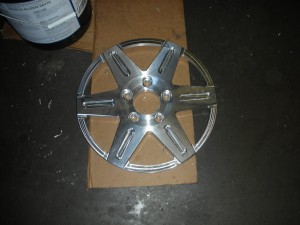
Some of the prettier aspects of the car should be coming together soon. These first two are of the Vintage Engineering magnesium wheels, after coming back from receiving their DOW 9 coating.
Ray at Vintage then drills for the Camaro bolt pattern, and removes the coating from the outer lips with a scotch-brite pad on a lathe. When done they look like the other two I’ve already received. When they’re all here, will get the vintage-style Avons mounted up and put on the car.
Those are just for the street and any show-type activities though. The ones below are the real deal race wheels. 18×9″ Jongbloed 214 Aero, with custom backspacing, different front and rear.
Jongbloed mounted up my first set of brand new shaved ST tires on those today, should have them this week. Congrats to Mike Heinitz for correctly identifying the wheel pattern after I showed them in process back here.
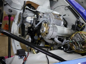
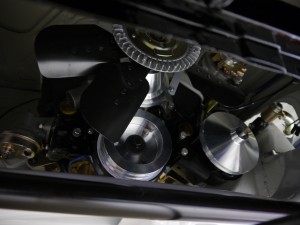
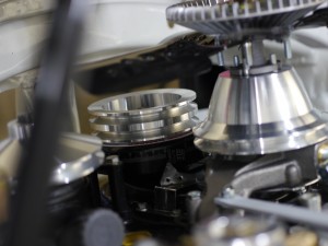
Below are a few of the engine compartment, coming together, for real this time! 🙂 The March Performance pulleys look really great – they add a pop of shine without the obnoxiousness of chrome, and don’t betray the simple mostly-stock, all-business look I’m after.
With any luck I’ll have some rollers on this thing for some out-in-the-driveway shots this weekend.
Front seats in
Another project that was a bunch more work than anticipated!
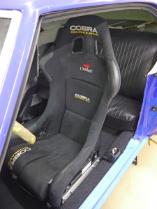
Driver’s seat I’ve had sitting on a shelf for a long time now. In the early days of part searching, came across my favorite autocross seat for sale – the Cobra Suzuka Technology.
It’s my favorite, because the Suzuka design offers superb lateral support, without all the big head-restricting elements found in dedicated roadrace seats. I ran a Suzuka in my 240sx and loved it. You can also pull out the bottom seat cushion to get even lower, which is great on course, then put it back in for extra comfort on the drive home.
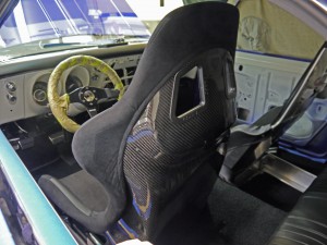
This is the fancier “Technology” version, that they only make to order. I found it second-hand, but brand new and never installed, from an NSX owner. The Technology version features carbon-fiber construction vs. Kevlar, has more durable wearing materials, and uses the same sort of fancy shape-remembering foam used in F1 cars. A cool seat!
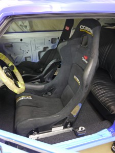
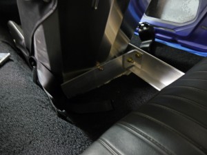
The seat mounts took a couple revisions. The bottom of this seat is a bit wider than most, so the popular brand Wedge Engineering said they couldn’t make brackets for it, after a couple calls. Instead, I bought a pair of Sparco’s universal sliders and fabbed the mounts myself. The seat is as low as it can get, while still allowing the slider lever mechanism to lift enough to let the seat move.
Hard to tell if it’s low enough, with the car still up in the air on jackstands. If not, I’ll have to forego the sliders, and attach it in a fixed position. I’m really not that tall (~5’7″) but like to sit lower and a bit further back while autocrossing than most people my height.
One advantage of going to fixed position for the driver’s seat, would be the possibility of the seat mount stiffening the car up a bit. For the passenger side I went with a classic Kirkey seat, again repeating what I did in the 240sx.
The Kirkey is great for a few reasons. It is easy to mount – basically pick your spots, drill some holes, and you’re done. It works great as a bucket for carrying things to/from events – pretty much every tire sprayer I’ve ever used leaks, but with it sitting in the passenger seat, the leak is contained in the seat itself, which is easy to dry out by removing the cover. Since it is aluminum, should be easy to attach a camera mount to when that time comes. It’s quite light at a bit over 16 pounds with cover. And lastly, it’s cheap!
In mounting, tied the beefy angle aluminum into the four factory mount points, in addition to a couple other secure spots. In ST our seat and mount combinations have to weigh at least 25 pounds, so this is a place where adding 9-10 pounds of bracing doesn’t come at any net weight cost the way “steelitis” items like the subframe connectors do.
This thing isn’t going anywhere in an incident! Have some future plans to add additional bracing for the “seat” but this is good enough for now.
Oil pan
Whew, that was a bear. Too bad ST didn’t allow aftermarket oil pans in 2010 when I had the motor built, or 2011 when I put it in… 😉
An oil pan swap can be done with the engine in the car, but it’s a bit of a pain, have to remove some things, jack it up under the old pan, use block to get it to stay up high, swap pans, and then lower back down.
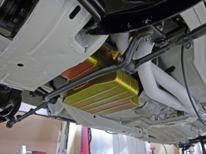
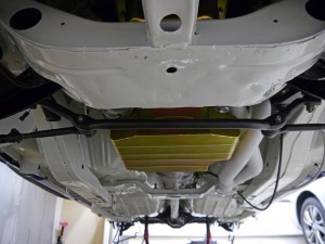
Was able to get the stock pan off without too much trouble, but the aftermarket pan I ended up using from Milodon, hangs down a bit lower than stock, requiring the motor be raised even further. Underside of the car as it looks today:
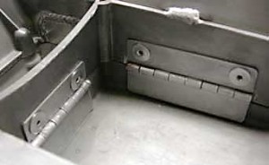
This pan has an increased oil capacity from stock (7 quarts vs. 4), left and right-side kick-outs (lots of circle-track stuff out there with only right-side), and three internal trap-door baffles. Here is a photo illustrating the concept (courtesy this Alfa Romeo site):
The principle with these doors, is they all hinge into a small central area where the oil pickup is located. They keep oil from rushing out as g-forces build in braking, cornering, or accelerating, and allow oil from the perimeter reservoirs to push the door open and flow into the pickup area.
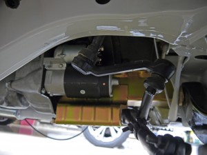
Even with as old and simple as this car is, there is still some fairly tight packaging at work. The pan gets very close to the steering, the headers, the monstrous stock starter, has a cutout for an oil filter, and just barely tucks up higher than the stock crossmember, while still being a little deeper than the stock pan.
With all its tricks, the pan should go a long way in helping ensure a steady supply of oil to the pump in big corners. Between the weight of the pan and extra oil there’s probably another 10 pounds on the nose of the car, uggg, but I’ll take it as good insurance. Will probably still run the Accusump accumulator at non-SCCA events for that extra measure of protection.
Playing with the front suspension
While I should have spent the day doing something awful like bending fuel lines or polishing up ancient vent window trim, instead spent it looking at the front suspension.
The car is now sitting on the suspension, with jackstands under the front control arms and rear axle. Trying to get the bushings and springs to settle a bit, and get an idea of how much they’ll compress under the car’s weight.
Front spring perches are at a height placing the car where I believe its static ride height will be once it’s on the ground. It has about 1.5″ until the control arm hits the frame, which out at the tire is over 2″ of bump travel. Should be plenty to handle what’s out there, assuming there aren’t any big tire rub issues that pop up first.
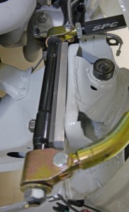
I put the driver’s side together with the camber (rear) portion of the adjustable upper control arms fully shortened, maximizing negative camber. The factory upper control arm had an effective length of ~9.5″. The SPC arms I’m using, when fully shortened, have an effective length of ~8.5″.
With offset bushings in the lower control arms, the SPC arm fully shortened, and the car at what I believe will be its static ride height, the front suspension showed only 2.5 degrees of negative camber! That might sound like a lot for those accustomed to primarily street cars, where anything more than -1 is oddball. But for a racer, -2.5 in front is just about the minimum on anything – it might just barely be enough if you have fantastic camber curves, no body roll, and tires that are accommodating of modest camber settings. But everybody else at the autocross uses more if they can get it, and in the case of catastrophically bad geometry and lots of weight on a floppy 265 street tire, I will need tons more.
Good news is there are a couple options. The factory describes using shims at the upper control arm mounting point, to add camber and/or caster. I have a bunch of 1/8″ shims on hand, but then decided to make my own out of aluminum stock:
The silver material is 1/2″ thick, the darker stuff, 1/4″. 3/4″ is about as far as you can safely go with the factory UCA fasteners.
In building the shims and measuring how they affected camber, I found that for each 1/8″ of shim, the car would gain about 1/2 a degree of negative camber. Those values should be handy for any of the guys running stock-height spindles and factory pickup points.
So together those two shims added 6/8ths, or 3 degrees negative, taking it to a static 5.5 degrees negative camber.
That number sounds really too far out there, and I certainly hope to find that’s the case. At this ride height, the outer pivot point of the upper control arm appears parallel, or perhaps just slightly above, the inner pivot point. This is a good thing, meaning the UCA will be pulling the top of the spindle “in”, in a manner that should produce favorable negative camber gain. However the lower control arm is definitely past parallel, with the lower ball joint a little bit above the inner pivot point. This means the suspension is also pulling in the lower part of the spindle, a camber-robbing direction.
One helpful element, is the lower control arm is effectively ~16″ long, whereas our SPC full-short arm is only ~8.5″. The smaller radius of the upper arm should product lateral (inward) movement more quickly compared to the lower arm, hopefully passing it somepoint soon, and generating some negative camber gain. One could do something like the Guldstrand Mod – it lowers the mounting point for the upper control arm, putting it in a steeper part of its travel, generating more camber gain. Unfortunately relocating pickup points is not only illegal in ST, it’s illegal in most forms of motorsport – at least those that don’t also allow for a complete tube frame chassis.
Since the upper control arm is in a beneficial part of its travel at this ride height (which I believe is just about on the bump stop in a stock car) – there may be a better way than shims. What if one could shorter the upper arm even more?
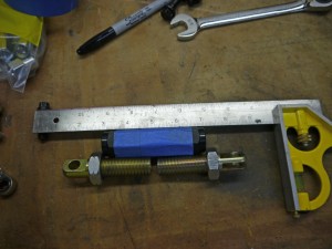
The turnbuckle for camber adjustment on the SPC arm is 4″ long as delievered from the supplier. SPC does not appear to make a shorter turnbuckle-
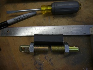
So I made one, by cutting down each end of the turnbuckle by 1/2″, and cutting down the threaded inserts by an equivalent amount. The result-
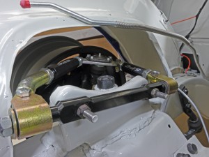
With the turnbuckle now 3″ in length, the upper control arm can be shortened to 7.5″ in length, less than half the length of the lower control arm. Here it is on the car:
No clearance issues anywhere I could see, fits fine even at full short. An added benefit I was noticing with the negative camber, is the lower ball joint appeared to sit at a more natural angle. The lower control arm has a bit of a tilt to it, and with the stock upper control arm at this ride height, the car would normally have its camber about eight degrees more positive than this, equating to an extra eight degree of tilt to an already outward-tilted ball joint.
Still, not sure I will need this much. Won’t know for sure until some testing and tuning is done. I ran about -4.5 degrees on my strut-suspended 240sx, but it had a very compromised suspension at the ride heights I used, only losing camber in bump. I’ll have to do some more measurements with the springs out, but there’s a chance with this upper arm, the car is at least not losing any camber.
As stated elsewhere in this blog, I’m a big believer in providing yourself with a wide range of adjustability. You don’t ever want to be at the extreme of any of your self-defined adjustment ranges, for what if “more” in a given tuning direction, was better? In this case with no shims and the upper arms full short, the car has a ”
“natural” negative camber setting of over six degrees (which I have seen people use on tracked E36 BMW race cars). By lengthening the upper arm, camber could be brought to zero, and with shims, could go even further negative, to up past 10 degrees, which I couldn’t ever see needing. There’s also the possibility, if the short arm length causes issues, where it could be lengthened, in concert with shims, to maintain the same static value, but change the dynamic geometry to something less aggressive in camber gain.
Hopefully this is enough to begin to tame the Camaro’s front suspension demons!
2 rule changes for 2013 – motor mounts and oil pans
The rules I have linked to here were for the 2011 season, and it’s looking like 2013 will be the first real season the car gets.
The SCCA released its October Fastrack recently, and besides the controversial classing of the new Scion/Subaru FT86 twins in STX, two new allowances were communicated.
One, the ST category is now free to run motor mounts of unrestricted origin, so long as they are no lighter than stock.
Two, the ST category is now allowed to run aftermarket oil pans and pickups.
The oil pan allowance will be a great help to the Camaro, as the car is not known for its good oil control from the factory, under heavy lateral loads. The motor mount allowance is less of a boon, but in theory, having the engine solidly mounted could contribute to overall vehicle stiffness, which is a weak point of the Camaro.
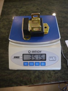
So solid mounts it is. First, I weighed the brand new Prothane mount as a baseline. The original motor mounts were long long gone, so I don’t know exactly what they weighed. The Prothane units are quite beefy, made of solid polyurethane, whereas factory mounts tend to be soft rubber with voids, allowing for more movement. I figure as long as my solid mounts weigh at least as much as the Prothane mounts, I’ll be ok. If anyone out there has a perfect OEM motor mount they can weigh, I’d appreciate it.
Here’s the Prothane, not light at over 35 ounces:
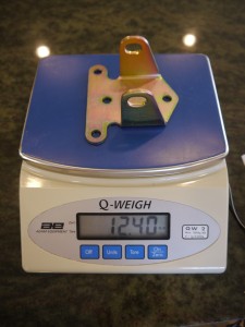
And here’s a new Moroso solid mount:
12.4 ounces, almost 23 ounces lighter, so between the two, almost 3 pounds difference! Ugg. Going to have to figure out how to add 3 pounds to these mounts to stay legal.
The oil pan is another project, haven’t quite started on yet.
It’s been two years!
Well, it’s officially been two years since I flew up to Sacramento to drive this thing home:
It’s come a long long way since then. I broke the project into five phases:
- Disassembly/teardown
- Fabrication
- Body & paint
- Assembly
- Tuning
Phase 1 finished pretty quickly, I had the car stripped to the shell and off to John Coffey for fabrication, in just over 2 months – November 2010.
Phase 2 took 5 months, to the end of April 2011. A little longer than I originally anticipated, though not really all that long in retrospect. There may be a couple other things I need to have John fab up for me, but the key chassis elements are done.
Phase 3 was the one I feared the most – “paint jail”. We’ve all heard stories of guys with project cars sent off to the body shop, never to return. Pat Smith of Pat’s Custom Cars did a fantastic job in producing a quick turnaround, he had the car a bit over 4 months. Some of the speed might have been due to the solidity of the base car – very little metal repairs were needed, all the original panels were kept intact. Car was hope by September of 2011.
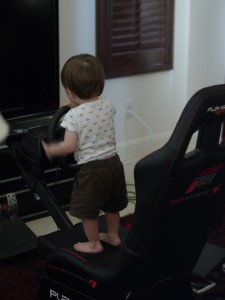
Phase 4 is where it’s been for the past year. Those that have done one of these can appreciate how long this part takes when you’re taking the time to “do it right”. Lots of things don’t fit right without a little tweaking, and it takes a long long time to get all the details done right. When you’re putting this much work into something, any little imperfect shortcut will be staring back at you forever. In addition to the sheer amount of work this step entails for me, life has been busy – the day job/career has been going well but consuming 60-70 hours/week pretty routinely. Earlier this year during my project’s pause, I started a new business and have been working to get it off the ground. Oh, and then there’s this guy:
What was a tiny few cells rapidly dividing when I bought the Camaro, is now almost one and a half years old.
Still chipping away at the to-do list. Even as things get knocked off, it hovers around 50 items long, as I discover new things along the way that need doing. I’ve also been cheating a bit, making some suspension tweaks along the way. Those parts could wait until after the car is on the road as part of the final Phase 5, but many of the tweaks are fun and simple to do, good projects when there’s only 30-40 minutes to work on things.
Usually after 2 years I’m thinking of moving on to something else – in this case, just getting started! The car should provide for a lot of fun for a long long time, in lots of different types of events.
To those that have been following the project this whole time, thanks for your patience!
First two “road & track” wheels arrived
Should go from having no wheels & tires, to two sets, in another week or two. Pleased to see these Vintage Engineering 15×8 wheels fit my aftermarket big brake setup front and rear.
These are the ones I’ll use up front, with 4.25″ backspace. With a 15″ wheel, that’s all you can go (maybe 4 3/8″ max) before you have interference with the outer steering boot. Rears will have a bit more backspace (4.75″) to help fit the big 275 rear tire.
The plan for these wheels is to use them on street and on the track, and for any show-type events. I’m not really a car show type of person, but with the right stickers, hoping it could pass as a Penske/Sunoco replica to the untrained eye.
Once the rear wheels arrive, will get the Avons mounted, and see how this thing looks on the ground! There’s a good chance my STX wheels and tires will be arriving at the same time, should make for a lot of fun photos!
Wheels getting made
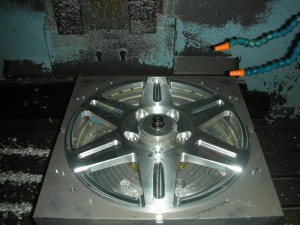
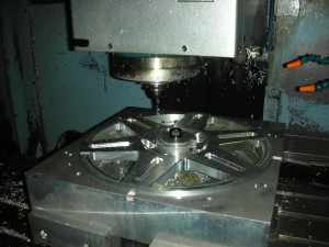
Finally some progress on my wheel manufacture, got a couple pics to share of the centers being made:
Can anyone guess the make and model?
