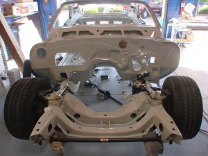
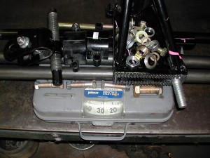
Headers back, couple minor things
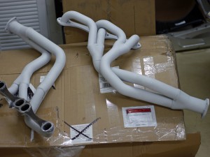
Headers made it back from Swaintech with their White Lightning coating.
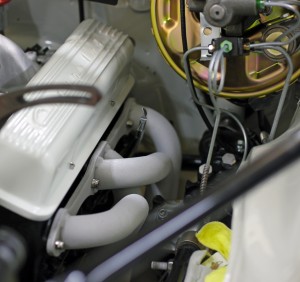
Again a very high quality result, and now that I see how close the headers run to critical components like the starter and power steering, am even more glad I went with it.
The coating itself should last a long long time, and help the neighboring components last longer too.
Thought I’d let the pimpy valve covers make their entry now. They’re the same off-white used everywhere else on the car, though they do look a little different here in the light.
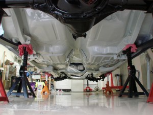
Still have a few little things to take care of on the underside of the car before the exhaust can go in, not the least of which is the remaining bends to make on the shifter linkage so it doesn’t bind itself up when in reverse.
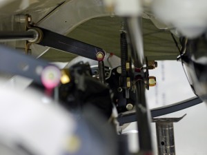
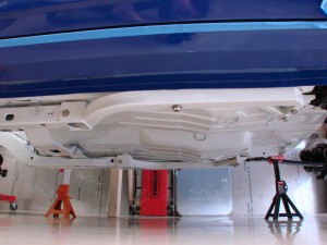
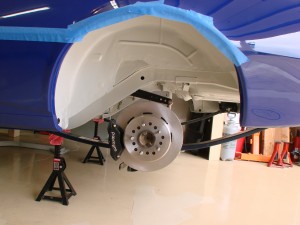
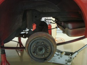
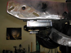
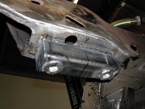
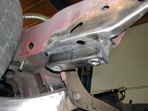
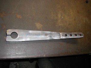
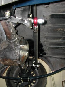
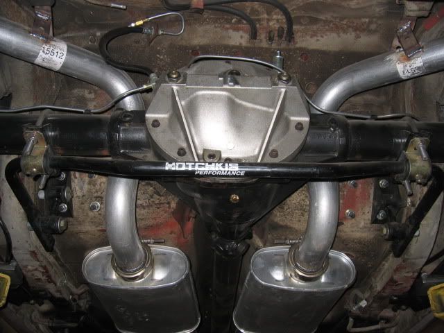
Out back, made a couple modifications to the rear swaybar, even though it hasn’t been used yet. One, was shortening the endlinks on both sides by about an inch. The second, was shortening the driver-side arm, so it’s the same length as the non-adjustable passenger side. These two changes should provide a lot more bump travel – with this arm length, the bar arm ends will contact the floor (if nothing else hits first) at its highest point, allowing for maximum travel. You can see it somewhat here:
A couple weeks ago I put together a to-do list of things I could think of off the top of my head. Presently it has 57 items, of which 7 have been done. 4 will require outside help – mount tires to wheels (which themselves haven’t even been made yet), add a slight bend to front swaybar arms (purchased a narrower front center section for the swaybar to allow for more tire clearance, but it requires modification to the arm shape), welding the alternator bracket to the header (found a bracket but should have it welded for better stability/reliability), and the headliner install. I could *try* the headliner install myself but everything I’ve seen says you need at least 2 people, if not 3. It’s not like newer stuff where it snaps in, it’s a real fabric thing with adhesive and these wacky metal rods. Looks like awful work.
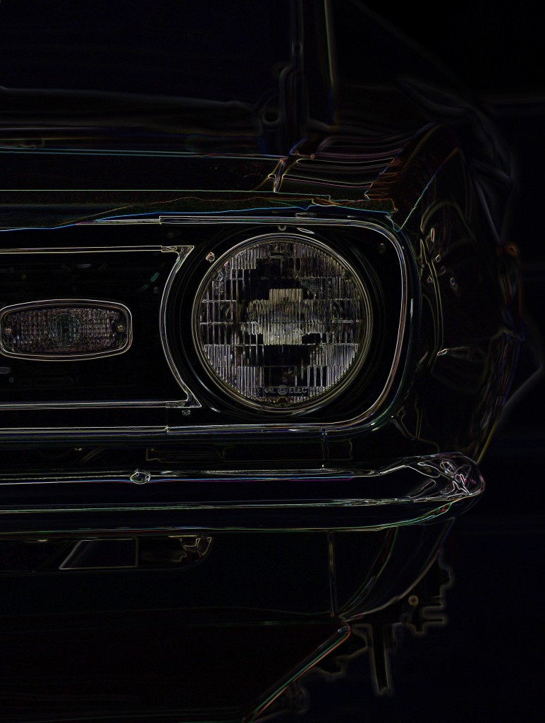
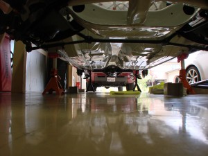
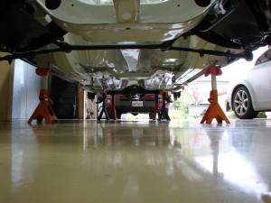
Each of the tasks on the list are 4-8 hours, so still a long way to go. Will try to take more pictures along the way. Here’s an artsy one in the meantime…
Call to arms
Steering arms, in this case.
For some time, been scouring the internet looking for a pair of original Z28 outer steering arms for the Camaro. These are extremely hard to find, and not currently reproduced. (Same story goes for the chrome portions of the ’67 vent windows, if anybody has a pair in good shape, please let me know).
David Pozzi put together as close to a complete detailing of Camaro steering components as exists on the internet here.
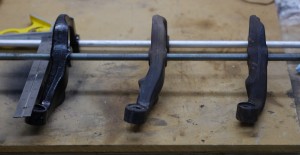
I now have three pairs of outer steering arms-
The leftmost arm is from Speedway Motors, which they are claimed would be shorter/faster than manual steer arms. Their product description:
Don’t know if you ever thought about this or not, but the steering arms on some cars were a different length depending if they were power or manual steering. The manual cars had a longer arm and if you convert them to power steering you still have slow steering. These forged arms are shorter (faster) than manual steering arms.
The middle arm is one I had on the car at purchase. The car was manual steer, and the state of everything gave me no reason to think any of those components had ever been changed.
The right arm is the more recent addition.
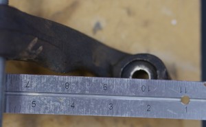
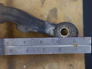
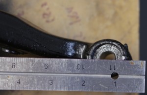
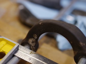
Used two 1/2″ rods to keep the arms aligned. Measurement is from the rear of the farthest hole. Angle on the square is up at 2″, so the actual distance measured is 2″ less than appears on the ruler. I’m looking at the distance from the “back” of the rearmost hole, to the “front” of the tie rod hole, maximizing the distance. Working back from right to left on actual lengths-
Rightmost arm: 8 1/8″ (part number 3954876)
Middle arm: 8 5/8″ (part number 3916266)
Leftmost arm: 9 1/8″ (Speedway part number 91034912)
Tsk tsk on Speedway – their arms are longer than manual steer arms! There is a clear 1/2″ difference in length with each arm. If Speedway had made their arms shorter than manual steer arms, they’d be just fine, but they did the opposite.
Why the fuss over 1/2″? A few reasons-
- The shorter outer arm length provides a quicker steering ratio. This means less steering input required for a given maneuver, and ultimately means less hand-over-hand, shuffle-steering maneuvers. I hate moving my hands on the wheel, and loathe the slow steering of cars like the E36 era BMWs.
- The shorter arm is less “in the way” of high offset wheels. Of course, “high” offset in the early Camaro world is anything above zero, but in general the shorter arms help you avoid this situation:
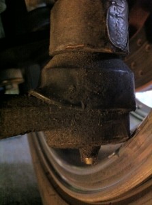
The dreaded tie-rod rub. The guys that run big bump steer spacers, get it worse. The above is not my car though ironically, the original steering arms had the tie rod rubbing the inside of the sidewall of 245-14 tires on the ’84 Berlinetta wheels I drove the car down from Sacramento on. Scary!
With the suspension all together, I’ve since measured for wheels with the manual steering arms, and the size of wheel I’d like to run in 18″, just barely clears in many places. With the shorter Z28 arms, I could theoretically fit 17″ wheels with similar clearance, at least to the tie rods.
- These arms are technically the correct part for the car. A big part of this exercise is to experience what it would be like, to drive a vintage Trans-Am Camaro built to SCCA STX rules. While I could probably get away with running one of the inferior arms under the “parts no longer available” allowance, it just wouldn’t be the same.
…
Sorry it’s been so long without an update everyone, still don’t plan on getting into full steam on this for another couple months. For those of you wanting to see progress that I didn’t run into at the SD National Tour or ET Pro Solo, you can thank your SCCA brethren for one of the most effective guilt trips I’ve ever been on the wrong side of…
Lots more to come!
Rear brakes and subframe connectors
Initial progress over the holiday weekend. Rear brakes (rotors and calipers) and subframe connectors got installed.
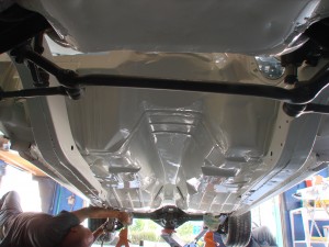
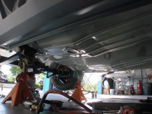
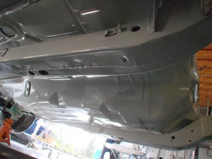
Before getting started on the connectors, decided to wax the underside of the car. Not that this is something I plan to do often (or perhaps, ever again), but it should help keep the underside clean, easy to wipe off any dirt and grime that lands there. With it all bare, this presented the last good opportunity for this extra protection before the car’s underside starts to get “busy” with plumbing and other equipment.
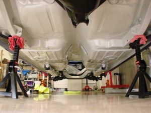
View from the rear-
And from the front-
And here, post-installation:
Can see they were painted the same light gray used elsewhere…figured they’d stick out if kept their original color:
From the side:
And the back:
And the brakes. I bought these a while back. Decided to stay with a modestly sized rotor (12.19″) as it allows for use of 15″ wheels for the real vintage look, if the situation ever warrants. For autocross, these are probably overkill, while being a little small for track duty. Thinking I would like to run the car at the track a little bit some day, Laguna Seca and maybe Streets of Willow. With its autocross geared rear end, it’ll only be good for about 115 in 4th gear, not enough for most tracks.
Compare to how things looked a year ago:
Another good thing about this kit, is there are several different Wilwood calipers that can mount in place with no other changes. Because we don’t have the ability to use proportioning valves in ST, changing calipers is a coarse way of adjusting bias. These calipers are 4-piston, but one of the larger 4-piston units; if there’s too much rear bias, I can go to a smaller 4-piston; if there’s too little, I can step up to a 6 piston.
Made some big orders over the weekend, a complete interior is on its way, along with a few race goodies. Particularly excited about the battery; wish this one had been out for the last couple ST cars I built!
Back on the ground
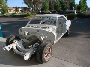
Got the body reacquainted with the front subframe and rearend today.
It all went pretty well, we made some good markers to help with subframe alignment so it could be brought right back where it needed to be.
Aren’t those wheels cool? Ha! The wheel/tire combo is actually about the right diameter overall, though I don’t think I’ll be going with 14’s. Lots of guys fixing up these cars are running brake rotors as big as those wheels!
Will be time to get the real rolling stock soon. I think I’ve decided on the wheels, and also the tires. Problem with ST is the stuff I buy today could be outdated for next season. Oh well…
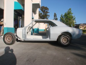
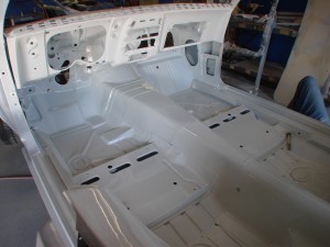
Getting an idea of the underbody and interior color yet?
Inside…
Firewall same color-
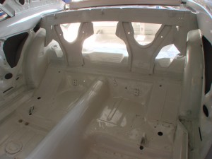
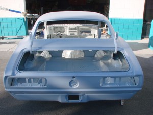
Trunk too
Tomorrow the doors, front end, and trunklid will get re-attached. Then the “real” body work can begin, fixing all the highs and lows, and straightening/evening all the gaps.
Can’t believe how quickly this thing is coming along!!!
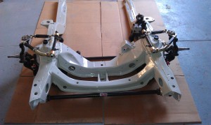
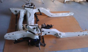
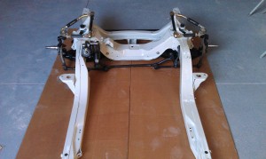
Front subframe
Still don’t have the correct outer steering arms, and no pitman arm, but this is a glimpse of where things are going.
Nothing all that exciting really. Can’t seam weld the subframe, as lots of people do. No Guldstrand mod (where the upper control arm mount points are re-drilled lower), steering is all stock stuff. Steering box is a rebuilt original 800 series, not the smaller and lighter 670 series most guys run. It’s heavy! Power steering adds almost 30 pounds to the car, all on the nose where it’s least desired…but I think with the big caster values I have planned, it’ll be necessary. The color looks almost white in these pics, though it’s actually a very light gray, custom blended. Perfect!
Oops
I received a really nice email today from a fellow named Louis, who pointed out an important oversight I’ve made. Specifically:
B. Suspension bushings may be replaced with bushings of any mate-
rials (except metal) as long as they fi t in the original location. Off-
set bushings may be used. In a replacement bushing the amount
of metal relative to the amount of nonmetallic material may not be
increased. This does not authorize a change in type of bushing (for
example ball and socket replacing a cylindrical bushing), or use of
a bushing with an angled hole whose direction differs from that of
the original bushing. If the Stock bushing accommodated multi-axis
motion via compliance of the component material(s), the replace-
ment bushing may not be changed to accommodate such motion
via a change in bushing type, for example to a spherical bearing or
similar component involving internal moving parts. Pins or keys may
be used to prevent the rotation of alternate bushings, but may serve
no other purpose than that of retaining the bushing in the desired
position.
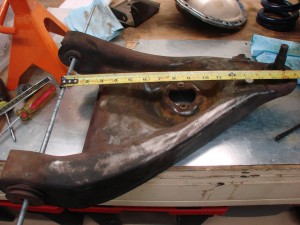
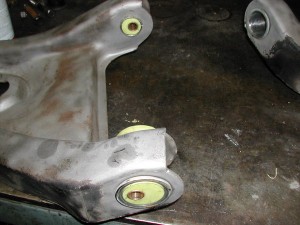
So yeah, um, that’s exactly what I just had made. Oops. John built them exactly as I asked, this was totally my bad.
I completely missed that bushing restriction when designing these pieces. That bushing rule is lengthy and difficult to pay attention to the whole way through. Of course I ought to know it a bit better as I’m on the STAC – the Street Touring Advisory Committee, the group of volunteers who works to maintain the ruleset for the Street Touring autocross category of preparation within the SCCA. Duhhh!
Many thanks to Louis for pointing this out to me! New custom bushings are going to cost a bunch of $, but I’d much rather this, than show up with an illegal car. Along those lines, if my readership spots anything I’m doing that’s blatantly illegal, please don’t be afraid to mention it to me. Part of what I hope to get from all the effort in creating this blog is help from its readers, in ensuring I’m doing this right. Or legally, at least.
The eagle has landed…then it took off again. Phase 3 begin
John Coffey of BetaMotorsports wrapped up his work a few weeks ago. I’ve been a bit busy with other things, so super stud man Ken Motonishi went and picked up the car for me.
The girlfriend was a bit disappointed as I rolled it back into the garage – “It looks the same as when it left!?”
To some extent she’s right, the car looks the same cosmetically. What John did, was build a solid chassis and suspension foundation underneath the body – one I can build upon, and tune to work the way I want it to. There were a few themes governing his work:
- Provide adjustability to every aspect of the suspension. The adjustability should allow for very fine increments of change, while also offering a wide enough range of adjustment to allow for a satisfactory setting in any of the situations the car might find itself in.
- Minimize weight gain through Steelitis. Every net addition would have to work hard to justify its existence.
- Do all this while fully complying with the SCCA Street Touring rules
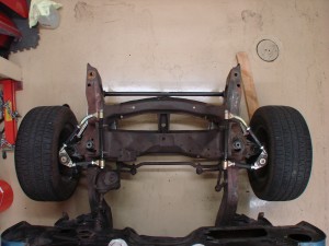
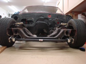
Here’s a couple pictures of the front end as it sat-
With this, the fabrication phase is complete, and phase 3, body and paint, can begin.
For this portion of the project, Pat Smith, a fellow member on http://www.pro-touring.com who owns a paint shop in nearby Ramona, will be doing the work. Pat has done some really great work on classic Camaros and Mustangs, and is excited to be a part of this project. I inquired with a couple different well-known shops in town, and Pat offered not only the best value, but also presented just the right sort of spirit and attitude I look for when looking for help.
Now when it comes to aesthetics, I have practically zero ability and am not afraid to admit so. It is time to decide what color things should be on the car, and in so doing I intend to plagiarize to the greatest extent possible from the car that inspired this project. I figure there’s enough trails blazed in other aspects of the car, there’s no need to reinvent the wheel here. Besides, there is a singular look to these cars that evokes the awe in me. That’ll be the look we aim for.
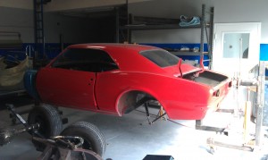
Pat picked the car up last Saturday, and as of last night, had already made some good progress:
He got the front and rear suspension removed, and the car mounted up on the rotisserie. That’s one advantage of going with somebody that’s done several of these cars before – they know them well, and have custom-made tools like the Camaro rotisserie, to aid in the job.
The car will get all its yucky red paint removed, then be thoroughly cleaned and inspected. As best we can tell the chassis appears practically rust-free, the paint removal this week will tell us for certain. From there it’s on to primer and panel fitment, and finally, paint. When it comes home from this phase, it is sure to look much much different!
I know a lot of people really like this phase of projects, so I’ll keep the pics coming as best I can. Getting a car to look good, and the panels to fit, is all voodoo and black magic, so I won’t have too much commentary to add. I will probably sort out the steering and knuckle situation while the car is being painted, so it can get rolled out of the shop with clean new Z28-spec stuff in place instead of the funky manual stuff on it now.
Front suspension – springs and bar
In keeping with the theme of providing adequate range of adjustability, the front suspension required a lot of work.
The geometric concerns (static caster, kingpin inclination, offset bushings) we covered before. In most cars you wouldn’t worry about that stuff, and could go straight to bolting on whatever coilovers you wanted. Ideally those coilovers would have a damper matched to the corner weights of your car, and the range of spring rates you’re likely to run.
As with everything else in Old Camaroville, such is not the case here. While the stock arrangement is a shock with a spring situated concentrically around it, we can’t convert to a simple coilover (yes, I wrote my letter to seb@scca.com asking them to say I could). The spring has to stay mounted to the arm. Coilovers are great because they’re a light and simple way of providing ride height adjustment. The first-gen Camaro comes from the factory with 5.5″ diameter springs, while coilovers can use 2.5″ or 2.25″ diameter springs, which weigh significantly less for the same spring rate, and are much more widely available.
So to get ride height adjustability (a critical thing to have), we have to build some kind of adjuster that retains the stock mount point on the arm.
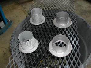
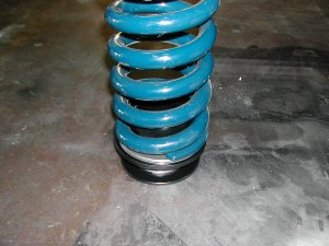
The circle-track world appears to come to the rescue again, Afco makes an inexpensive threaded adjuster for 5″ or 5.5″ springs. The problem is, they didn’t design their part to work with the “really high” spring rate I’m starting with (which isn’t even the stiffest off-the-shelf spring Hypercoil makes in 5.5″) – the “wire” in the spring is so thick, its ID interferes with the centering cylinder in the adjuster. So more work for John, who first has to remove the faux cad coating from the parts-
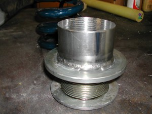
And then he has to cut off the original centering cylinders (the vertical part, in the two shorter pieces above), and weld in a new cylinder with a smaller OD, to accommodate the big fat coils
Hooray, the 5.5″ spring now fits the 5.5″ adjuster!
From there, he works to get them attached to the lower control arm in a secure fashion-
The two bolts holding the spring adjuster go through the original holes in the arm, and integrate with the new lower shock mount brackets
(shocks themselves are still a ways away from completion, will come later)
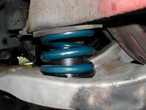
Here’s the adjuster at its lowest position. There’s 2-3″ it can move upwards from here. If this isn’t low enough, then I make the springs shorter!
The stock upper spring seat is retained, which works well with the Hypercoil springs. The stock springs are “open” at both ends, and have curved pockets to sit in at both ends. The Hyperco springs are closed/flat at one end, open on the other – which suits their new flat lower seat, and stock curved upper seat, perfectly.
The above pic doesn’t look all that jaw-dropping but is the culmination of a whole lot of work. All you people out there with easy to adjust ride height, don’t take it for granted!
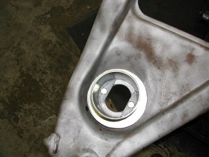
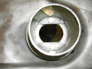
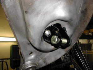
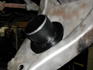
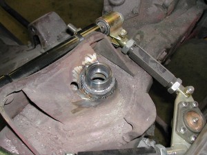
Up top, the stock upper shock mount (aka “a hole”) was modified with a retaining cup.
This will allow for the shock to be retained at that end with a circlip and spherical bearing – a much better solution the stock solution, which resembles a skewer through two marshmallows.
So that’s the spring adjustment mechanism, and the new shock mounts, which will allow me to re-use my 28-series Konis pulled from the Viper. I’ve been very happy with the shocks, and with ProPartsUSA as a provider of shock service. In addition to excellent performance, a nice thing about the 28’s is their modularity – on the Viper they used spherical eyelets top and bottom, but without too much effort (or additional $), they can be modified to use this bayonet-style upper mount. In a lot of cases, you’d just have to punt and buy new shocks.
Next thing is the front swaybar. As with the rear, I wasn’t really happy with any of the available solutions. Most offer no means of adjustment, use mushy rubber or poly mounts, and crummy endlinks.
Again I went to the Speedway-style bar. With multiple holes in the arm, I can fine-tune bar stiffness, and with a replacement center section (~$100), I can perform larger adjustments, moving the whole range up or down. With bearing chassis mounts and spherical endlinks, slop and inconsistency is minimized.
The arm needed to be spaced down a bit to clear the frame rails and engine compartment components
The arms themselves are steel – a bit heavier than their aluminum alternatives, but work better when you need to make a bend or two-
Sighting down the arm prior to hookup
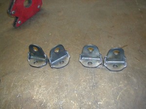
Endlink receiving brackets were fabricated and welded to each lower control arm. As with the rear, the adjustable end is put on the driver’s side.
And here she is, all put together!
At this point, Phase 2 (fabrication) is really truly close to being complete! It has been exciting to see imagination manifest in metal.
Rear sway bar
Some people try to get away without a rear sway bar on these cars. In some ways not having the bar is better, as it’s less weight, the rear suspension is a bit more free to move, and maybe it helps the car put power down better.
At the same time, there aren’t a ton of options out there for rear leaf springs. Anything stiffer than this will either be steel and super heavy, or a custom composite which is going to be a super expensive.
One thing you *must* be able to do, is tune the car to be its best, on a variety of surfaces under a variety of conditions. The more adjustments you can make, and the wider their range of adjustment, the more likely it is you’ll be able to find a spot in the overall adjustment spectrum, that suits the situation. Nothing should ever be at its limit of adjustment – what if more would be better? Without the ability to adjust the rear alignment in this live-axle dinosaur (a critical thing in powerful RWD cars), you need to have some other options at your disposal. In comes in the rear bar.
As with the panhard, nothing off the shelf was really very good. Every bar I’ve seen for these cars hangs down below the axle like so:
With this design, as the axle moves up and down, so does almost the entire weight of the rear sway bar…more dreaded Steelitis, in one of its worst forms, unsprung weight.
Much better to get the bulk of the bar on the chassis, with just the bar’s arms moving up and down with suspension movement. Just a design change can mean 10 pounds saved in unsprung weight. The other thing with this sort of bar, you’ve got a little bit of adjustment with arm lengths, but that’s it.
I am a tremendous believer in the Speedway (http://www.1speedway.com) style modular sway bars. With them, you can get some adjustments in the arm length, but also in the sitffness (outside diameter and wall thickness) of the center section. With a new $100 center section, you can shift your adjustment range up or down, without having to buy a whole new bar.
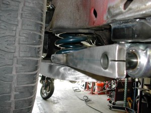
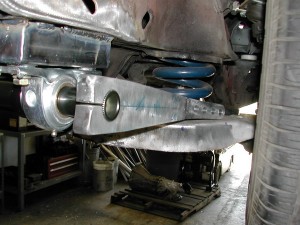
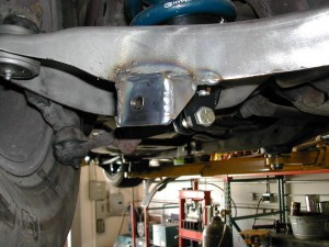
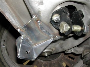
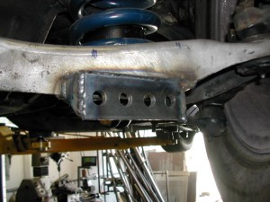
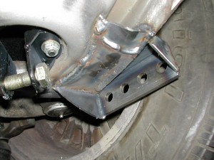
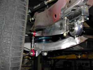
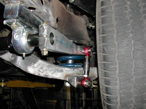
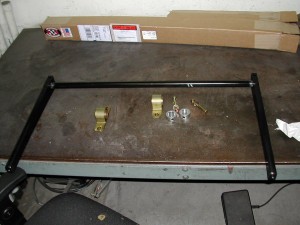
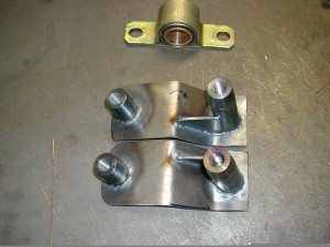
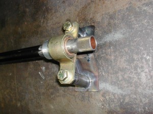
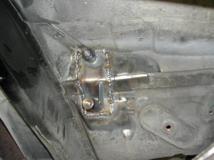
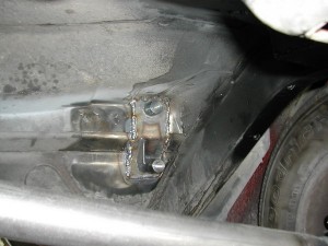
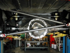
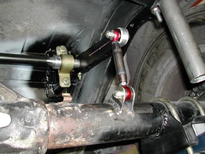
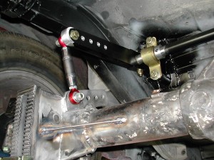
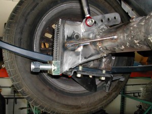
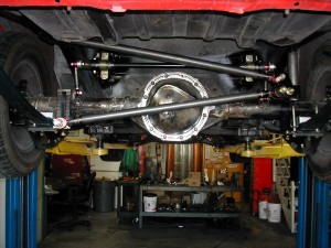
John found a place to mount the bar forward of the rear end, on the chassis. This required fabricating some custom mounts, welding them onto the car, and welding some mounts onto the axle. Letting the pictures talk-
And the endlinks, adjustable on the driver side.
The bar itself is a 1″ center, the arms aluminum, and the bearings bronze, so it’s not too heavy. Lots of adjustment on driver side arm, and the ability to increase or decrease the adjustment range, with different center sections.
Panhard completion
One bummer thing is there really doesn’t seem to be anything out there for the car that’s good as is. Everything needs modification.
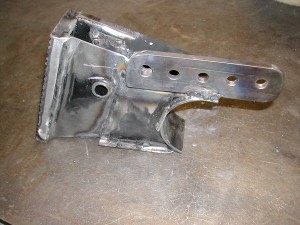
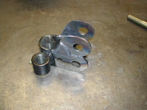
The panhard bar mounts from UB had a couple shortcomings. One, the axle-side mounts were really big and heavy, with all sorts of clamps and things. With it welded on, a lot less material is needed. So John hacked off a bunch of unnecessary material, and welded the puppy on there. Before:

After:
On the axle:
Those changes took a few pounds off the panhard parts, which means a few fewer pounds of unsprung weight. Another thing I see on so many of these cars is a truckload of parts bolted/welded to the rear axle (evil Steelitis rearing its ugly head again!). Sure, 5 new links and an 8 foot torque arm may control the axle well, but is it really worth another 75 pounds of unsprung weight to track over every bump?
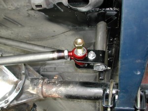
Another problem was the way the UB Machine chassis-side mount received the lateral loads from the panhard bar. Recall this pic from before:
The lateral compression/tension loads from the panhard aren’t in line with the vertical piece coming down from the chassis, or the cross brace. I was worried about the lateral loads causing the panhard mount piece to want to “twist” around the tubular down tube.
So out come the grinder and welder again, to modify that piece, to direct the loads into the chassis down tube, in the way I’d like to see.
This keeps the panhard in line with the support cross brace-
And in line with the support piece-
So now, the panhard rod is done. Swaybar in next post…
