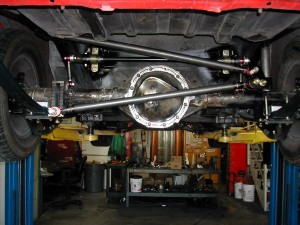
Front suspension – springs and bar
In keeping with the theme of providing adequate range of adjustability, the front suspension required a lot of work.
The geometric concerns (static caster, kingpin inclination, offset bushings) we covered before. In most cars you wouldn’t worry about that stuff, and could go straight to bolting on whatever coilovers you wanted. Ideally those coilovers would have a damper matched to the corner weights of your car, and the range of spring rates you’re likely to run.
As with everything else in Old Camaroville, such is not the case here. While the stock arrangement is a shock with a spring situated concentrically around it, we can’t convert to a simple coilover (yes, I wrote my letter to seb@scca.com asking them to say I could). The spring has to stay mounted to the arm. Coilovers are great because they’re a light and simple way of providing ride height adjustment. The first-gen Camaro comes from the factory with 5.5″ diameter springs, while coilovers can use 2.5″ or 2.25″ diameter springs, which weigh significantly less for the same spring rate, and are much more widely available.
So to get ride height adjustability (a critical thing to have), we have to build some kind of adjuster that retains the stock mount point on the arm.
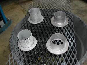
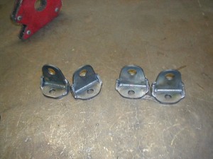
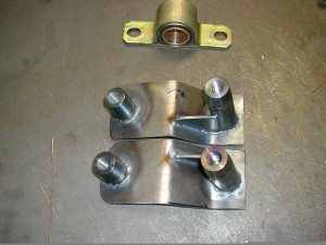
The circle-track world appears to come to the rescue again, Afco makes an inexpensive threaded adjuster for 5″ or 5.5″ springs. The problem is, they didn’t design their part to work with the “really high” spring rate I’m starting with (which isn’t even the stiffest off-the-shelf spring Hypercoil makes in 5.5″) – the “wire” in the spring is so thick, its ID interferes with the centering cylinder in the adjuster. So more work for John, who first has to remove the faux cad coating from the parts-
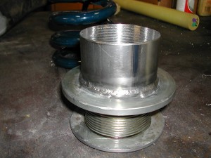
And then he has to cut off the original centering cylinders (the vertical part, in the two shorter pieces above), and weld in a new cylinder with a smaller OD, to accommodate the big fat coils
Hooray, the 5.5″ spring now fits the 5.5″ adjuster!
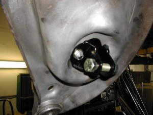
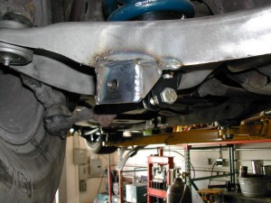
From there, he works to get them attached to the lower control arm in a secure fashion-
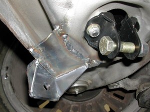
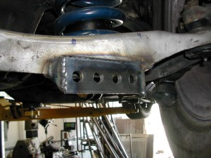
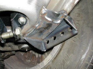
The two bolts holding the spring adjuster go through the original holes in the arm, and integrate with the new lower shock mount brackets
(shocks themselves are still a ways away from completion, will come later)
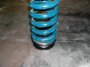
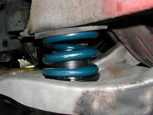
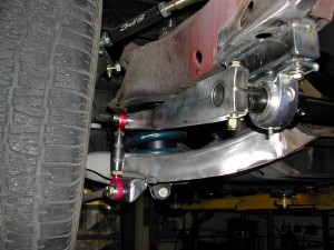
Here’s the adjuster at its lowest position. There’s 2-3″ it can move upwards from here. If this isn’t low enough, then I make the springs shorter! 🙂
The stock upper spring seat is retained, which works well with the Hypercoil springs. The stock springs are “open” at both ends, and have curved pockets to sit in at both ends. The Hyperco springs are closed/flat at one end, open on the other – which suits their new flat lower seat, and stock curved upper seat, perfectly.
The above pic doesn’t look all that jaw-dropping but is the culmination of a whole lot of work. All you people out there with easy to adjust ride height, don’t take it for granted! 🙂
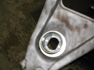
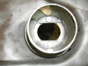
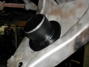
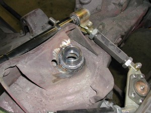
Up top, the stock upper shock mount (aka “a hole”) was modified with a retaining cup.
This will allow for the shock to be retained at that end with a circlip and spherical bearing – a much better solution the stock solution, which resembles a skewer through two marshmallows.
So that’s the spring adjustment mechanism, and the new shock mounts, which will allow me to re-use my 28-series Konis pulled from the Viper. I’ve been very happy with the shocks, and with ProPartsUSA as a provider of shock service. In addition to excellent performance, a nice thing about the 28’s is their modularity – on the Viper they used spherical eyelets top and bottom, but without too much effort (or additional $), they can be modified to use this bayonet-style upper mount. In a lot of cases, you’d just have to punt and buy new shocks.
Next thing is the front swaybar. As with the rear, I wasn’t really happy with any of the available solutions. Most offer no means of adjustment, use mushy rubber or poly mounts, and crummy endlinks.
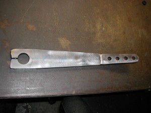
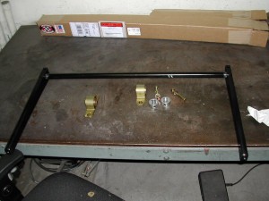
Again I went to the Speedway-style bar. With multiple holes in the arm, I can fine-tune bar stiffness, and with a replacement center section (~$100), I can perform larger adjustments, moving the whole range up or down. With bearing chassis mounts and spherical endlinks, slop and inconsistency is minimized.
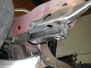
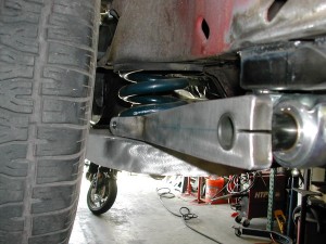
The arm needed to be spaced down a bit to clear the frame rails and engine compartment components
The arms themselves are steel – a bit heavier than their aluminum alternatives, but work better when you need to make a bend or two-
Sighting down the arm prior to hookup
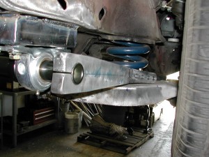
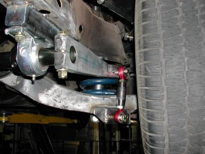
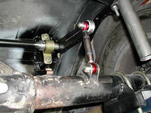
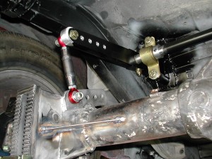
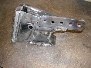
Endlink receiving brackets were fabricated and welded to each lower control arm. As with the rear, the adjustable end is put on the driver’s side.
And here she is, all put together!
At this point, Phase 2 (fabrication) is really truly close to being complete! It has been exciting to see imagination manifest in metal.
Rear sway bar
Some people try to get away without a rear sway bar on these cars. In some ways not having the bar is better, as it’s less weight, the rear suspension is a bit more free to move, and maybe it helps the car put power down better.
At the same time, there aren’t a ton of options out there for rear leaf springs. Anything stiffer than this will either be steel and super heavy, or a custom composite which is going to be a super expensive.
One thing you *must* be able to do, is tune the car to be its best, on a variety of surfaces under a variety of conditions. The more adjustments you can make, and the wider their range of adjustment, the more likely it is you’ll be able to find a spot in the overall adjustment spectrum, that suits the situation. Nothing should ever be at its limit of adjustment – what if more would be better? Without the ability to adjust the rear alignment in this live-axle dinosaur (a critical thing in powerful RWD cars), you need to have some other options at your disposal. In comes in the rear bar.
As with the panhard, nothing off the shelf was really very good. Every bar I’ve seen for these cars hangs down below the axle like so:
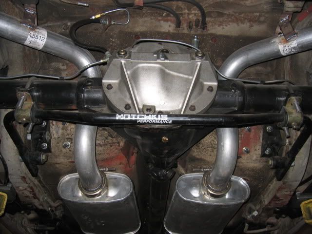
With this design, as the axle moves up and down, so does almost the entire weight of the rear sway bar…more dreaded Steelitis, in one of its worst forms, unsprung weight.
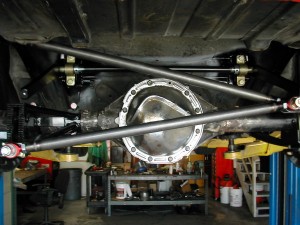
Much better to get the bulk of the bar on the chassis, with just the bar’s arms moving up and down with suspension movement. Just a design change can mean 10 pounds saved in unsprung weight. The other thing with this sort of bar, you’ve got a little bit of adjustment with arm lengths, but that’s it.
I am a tremendous believer in the Speedway (http://www.1speedway.com) style modular sway bars. With them, you can get some adjustments in the arm length, but also in the sitffness (outside diameter and wall thickness) of the center section. With a new $100 center section, you can shift your adjustment range up or down, without having to buy a whole new bar.
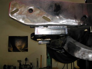
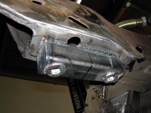
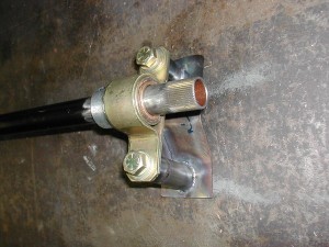
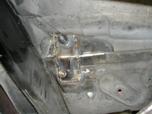
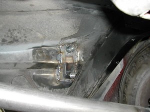
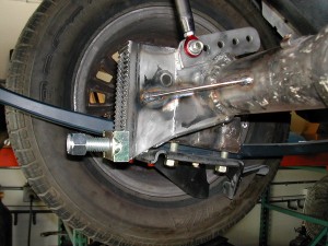
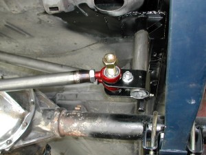
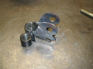
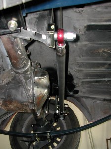
John found a place to mount the bar forward of the rear end, on the chassis. This required fabricating some custom mounts, welding them onto the car, and welding some mounts onto the axle. Letting the pictures talk-
And the endlinks, adjustable on the driver side.
The bar itself is a 1″ center, the arms aluminum, and the bearings bronze, so it’s not too heavy. Lots of adjustment on driver side arm, and the ability to increase or decrease the adjustment range, with different center sections.
Panhard completion
One bummer thing is there really doesn’t seem to be anything out there for the car that’s good as is. Everything needs modification.
The panhard bar mounts from UB had a couple shortcomings. One, the axle-side mounts were really big and heavy, with all sorts of clamps and things. With it welded on, a lot less material is needed. So John hacked off a bunch of unnecessary material, and welded the puppy on there. Before:

After:
On the axle:
Those changes took a few pounds off the panhard parts, which means a few fewer pounds of unsprung weight. Another thing I see on so many of these cars is a truckload of parts bolted/welded to the rear axle (evil Steelitis rearing its ugly head again!). Sure, 5 new links and an 8 foot torque arm may control the axle well, but is it really worth another 75 pounds of unsprung weight to track over every bump?
Another problem was the way the UB Machine chassis-side mount received the lateral loads from the panhard bar. Recall this pic from before:
The lateral compression/tension loads from the panhard aren’t in line with the vertical piece coming down from the chassis, or the cross brace. I was worried about the lateral loads causing the panhard mount piece to want to “twist” around the tubular down tube.
So out come the grinder and welder again, to modify that piece, to direct the loads into the chassis down tube, in the way I’d like to see.
This keeps the panhard in line with the support cross brace-
And in line with the support piece-
So now, the panhard rod is done. Swaybar in next post…
