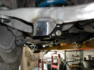
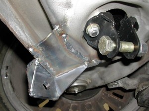
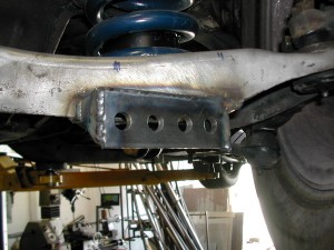
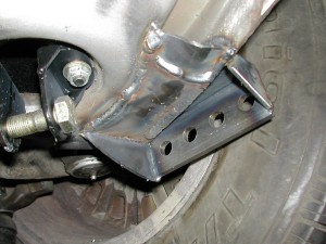
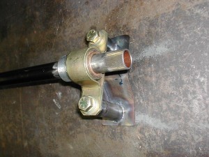
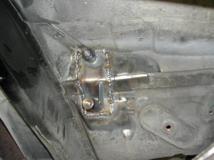
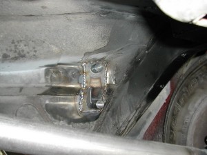
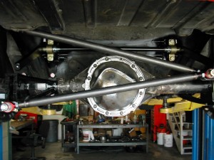
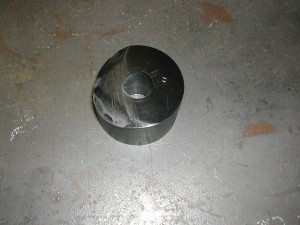
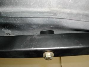
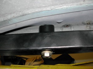
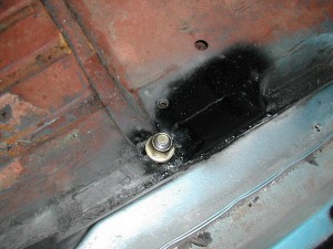
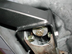
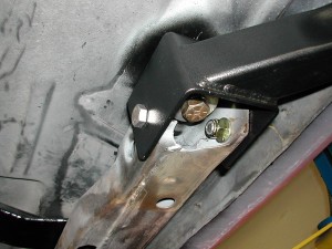
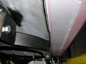
Oops
I received a really nice email today from a fellow named Louis, who pointed out an important oversight I’ve made. Specifically:
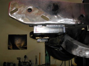
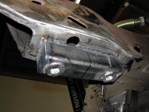
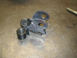
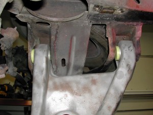
B. Suspension bushings may be replaced with bushings of any mate-
rials (except metal) as long as they fi t in the original location. Off-
set bushings may be used. In a replacement bushing the amount
of metal relative to the amount of nonmetallic material may not be
increased. This does not authorize a change in type of bushing (for
example ball and socket replacing a cylindrical bushing), or use of
a bushing with an angled hole whose direction differs from that of
the original bushing. If the Stock bushing accommodated multi-axis
motion via compliance of the component material(s), the replace-
ment bushing may not be changed to accommodate such motion
via a change in bushing type, for example to a spherical bearing or
similar component involving internal moving parts. Pins or keys may
be used to prevent the rotation of alternate bushings, but may serve
no other purpose than that of retaining the bushing in the desired
position.
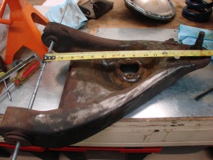
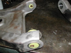
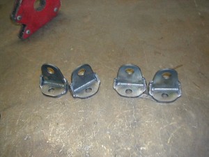
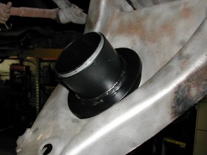
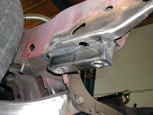
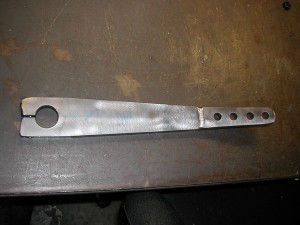
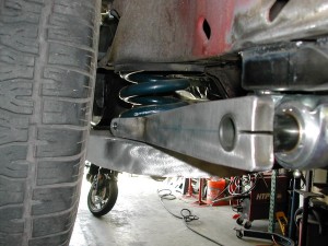
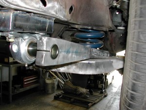
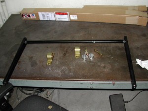
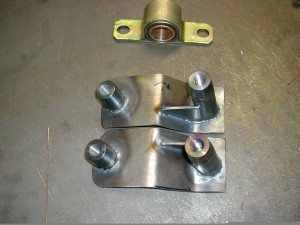
So yeah, um, that’s exactly what I just had made. Oops. John built them exactly as I asked, this was totally my bad.
I completely missed that bushing restriction when designing these pieces. That bushing rule is lengthy and difficult to pay attention to the whole way through. Of course I ought to know it a bit better as I’m on the STAC – the Street Touring Advisory Committee, the group of volunteers who works to maintain the ruleset for the Street Touring autocross category of preparation within the SCCA. Duhhh!
Many thanks to Louis for pointing this out to me! New custom bushings are going to cost a bunch of $, but I’d much rather this, than show up with an illegal car. Along those lines, if my readership spots anything I’m doing that’s blatantly illegal, please don’t be afraid to mention it to me. Part of what I hope to get from all the effort in creating this blog is help from its readers, in ensuring I’m doing this right. Or legally, at least. 🙂
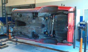
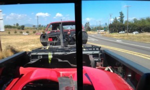
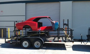
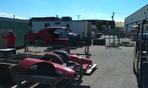
On rotisserie, to media blaster
Not much commentary here, they’re self explanatory. Rotating the car around on a rotisserie will help ensure a minimum amount of media gets trapped in the nooks and crannies.
The eagle has landed…then it took off again. Phase 3 begin
John Coffey of BetaMotorsports wrapped up his work a few weeks ago. I’ve been a bit busy with other things, so super stud man Ken Motonishi went and picked up the car for me.
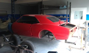
The girlfriend was a bit disappointed as I rolled it back into the garage – “It looks the same as when it left!?”
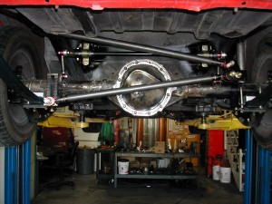
To some extent she’s right, the car looks the same cosmetically. What John did, was build a solid chassis and suspension foundation underneath the body – one I can build upon, and tune to work the way I want it to. There were a few themes governing his work:
- Provide adjustability to every aspect of the suspension. The adjustability should allow for very fine increments of change, while also offering a wide enough range of adjustment to allow for a satisfactory setting in any of the situations the car might find itself in.
- Minimize weight gain through Steelitis. Every net addition would have to work hard to justify its existence.
- Do all this while fully complying with the SCCA Street Touring rules
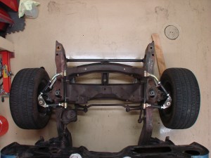
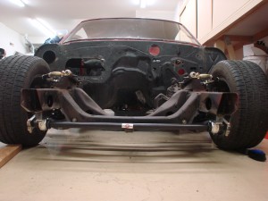
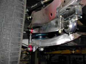
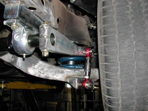
Here’s a couple pictures of the front end as it sat-
With this, the fabrication phase is complete, and phase 3, body and paint, can begin.
For this portion of the project, Pat Smith, a fellow member on http://www.pro-touring.com who owns a paint shop in nearby Ramona, will be doing the work. Pat has done some really great work on classic Camaros and Mustangs, and is excited to be a part of this project. I inquired with a couple different well-known shops in town, and Pat offered not only the best value, but also presented just the right sort of spirit and attitude I look for when looking for help.
Now when it comes to aesthetics, I have practically zero ability and am not afraid to admit so. It is time to decide what color things should be on the car, and in so doing I intend to plagiarize to the greatest extent possible from the car that inspired this project. I figure there’s enough trails blazed in other aspects of the car, there’s no need to reinvent the wheel here. Besides, there is a singular look to these cars that evokes the awe in me. That’ll be the look we aim for.
Pat picked the car up last Saturday, and as of last night, had already made some good progress:
He got the front and rear suspension removed, and the car mounted up on the rotisserie. That’s one advantage of going with somebody that’s done several of these cars before – they know them well, and have custom-made tools like the Camaro rotisserie, to aid in the job.
The car will get all its yucky red paint removed, then be thoroughly cleaned and inspected. As best we can tell the chassis appears practically rust-free, the paint removal this week will tell us for certain. From there it’s on to primer and panel fitment, and finally, paint. When it comes home from this phase, it is sure to look much much different!
I know a lot of people really like this phase of projects, so I’ll keep the pics coming as best I can. Getting a car to look good, and the panels to fit, is all voodoo and black magic, so I won’t have too much commentary to add. I will probably sort out the steering and knuckle situation while the car is being painted, so it can get rolled out of the shop with clean new Z28-spec stuff in place instead of the funky manual stuff on it now.
Front suspension – springs and bar
In keeping with the theme of providing adequate range of adjustability, the front suspension required a lot of work.
The geometric concerns (static caster, kingpin inclination, offset bushings) we covered before. In most cars you wouldn’t worry about that stuff, and could go straight to bolting on whatever coilovers you wanted. Ideally those coilovers would have a damper matched to the corner weights of your car, and the range of spring rates you’re likely to run.
As with everything else in Old Camaroville, such is not the case here. While the stock arrangement is a shock with a spring situated concentrically around it, we can’t convert to a simple coilover (yes, I wrote my letter to seb@scca.com asking them to say I could). The spring has to stay mounted to the arm. Coilovers are great because they’re a light and simple way of providing ride height adjustment. The first-gen Camaro comes from the factory with 5.5″ diameter springs, while coilovers can use 2.5″ or 2.25″ diameter springs, which weigh significantly less for the same spring rate, and are much more widely available.
So to get ride height adjustability (a critical thing to have), we have to build some kind of adjuster that retains the stock mount point on the arm.
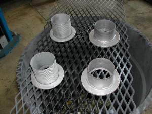
The circle-track world appears to come to the rescue again, Afco makes an inexpensive threaded adjuster for 5″ or 5.5″ springs. The problem is, they didn’t design their part to work with the “really high” spring rate I’m starting with (which isn’t even the stiffest off-the-shelf spring Hypercoil makes in 5.5″) – the “wire” in the spring is so thick, its ID interferes with the centering cylinder in the adjuster. So more work for John, who first has to remove the faux cad coating from the parts-
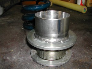
And then he has to cut off the original centering cylinders (the vertical part, in the two shorter pieces above), and weld in a new cylinder with a smaller OD, to accommodate the big fat coils
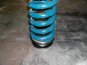
Hooray, the 5.5″ spring now fits the 5.5″ adjuster!
From there, he works to get them attached to the lower control arm in a secure fashion-
The two bolts holding the spring adjuster go through the original holes in the arm, and integrate with the new lower shock mount brackets
(shocks themselves are still a ways away from completion, will come later)
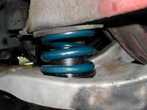
Here’s the adjuster at its lowest position. There’s 2-3″ it can move upwards from here. If this isn’t low enough, then I make the springs shorter! 🙂
The stock upper spring seat is retained, which works well with the Hypercoil springs. The stock springs are “open” at both ends, and have curved pockets to sit in at both ends. The Hyperco springs are closed/flat at one end, open on the other – which suits their new flat lower seat, and stock curved upper seat, perfectly.
The above pic doesn’t look all that jaw-dropping but is the culmination of a whole lot of work. All you people out there with easy to adjust ride height, don’t take it for granted! 🙂
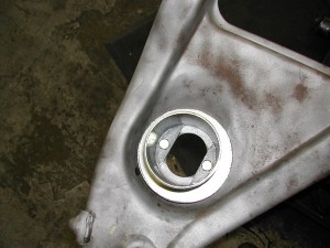
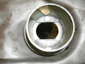
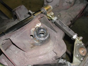
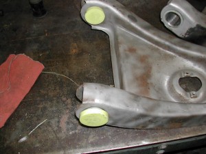
Up top, the stock upper shock mount (aka “a hole”) was modified with a retaining cup.
This will allow for the shock to be retained at that end with a circlip and spherical bearing – a much better solution the stock solution, which resembles a skewer through two marshmallows.
So that’s the spring adjustment mechanism, and the new shock mounts, which will allow me to re-use my 28-series Konis pulled from the Viper. I’ve been very happy with the shocks, and with ProPartsUSA as a provider of shock service. In addition to excellent performance, a nice thing about the 28’s is their modularity – on the Viper they used spherical eyelets top and bottom, but without too much effort (or additional $), they can be modified to use this bayonet-style upper mount. In a lot of cases, you’d just have to punt and buy new shocks.
Next thing is the front swaybar. As with the rear, I wasn’t really happy with any of the available solutions. Most offer no means of adjustment, use mushy rubber or poly mounts, and crummy endlinks.
Again I went to the Speedway-style bar. With multiple holes in the arm, I can fine-tune bar stiffness, and with a replacement center section (~$100), I can perform larger adjustments, moving the whole range up or down. With bearing chassis mounts and spherical endlinks, slop and inconsistency is minimized.
The arm needed to be spaced down a bit to clear the frame rails and engine compartment components
The arms themselves are steel – a bit heavier than their aluminum alternatives, but work better when you need to make a bend or two-
Sighting down the arm prior to hookup
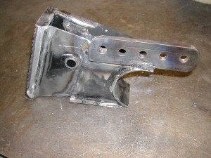
Endlink receiving brackets were fabricated and welded to each lower control arm. As with the rear, the adjustable end is put on the driver’s side.
And here she is, all put together!
At this point, Phase 2 (fabrication) is really truly close to being complete! It has been exciting to see imagination manifest in metal.
Rear sway bar
Some people try to get away without a rear sway bar on these cars. In some ways not having the bar is better, as it’s less weight, the rear suspension is a bit more free to move, and maybe it helps the car put power down better.
At the same time, there aren’t a ton of options out there for rear leaf springs. Anything stiffer than this will either be steel and super heavy, or a custom composite which is going to be a super expensive.
One thing you *must* be able to do, is tune the car to be its best, on a variety of surfaces under a variety of conditions. The more adjustments you can make, and the wider their range of adjustment, the more likely it is you’ll be able to find a spot in the overall adjustment spectrum, that suits the situation. Nothing should ever be at its limit of adjustment – what if more would be better? Without the ability to adjust the rear alignment in this live-axle dinosaur (a critical thing in powerful RWD cars), you need to have some other options at your disposal. In comes in the rear bar.
As with the panhard, nothing off the shelf was really very good. Every bar I’ve seen for these cars hangs down below the axle like so:
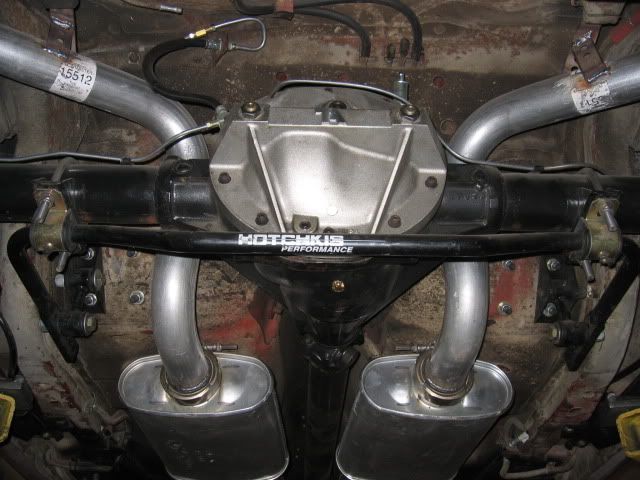
With this design, as the axle moves up and down, so does almost the entire weight of the rear sway bar…more dreaded Steelitis, in one of its worst forms, unsprung weight.
Much better to get the bulk of the bar on the chassis, with just the bar’s arms moving up and down with suspension movement. Just a design change can mean 10 pounds saved in unsprung weight. The other thing with this sort of bar, you’ve got a little bit of adjustment with arm lengths, but that’s it.
I am a tremendous believer in the Speedway (http://www.1speedway.com) style modular sway bars. With them, you can get some adjustments in the arm length, but also in the sitffness (outside diameter and wall thickness) of the center section. With a new $100 center section, you can shift your adjustment range up or down, without having to buy a whole new bar.
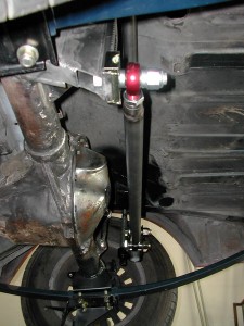
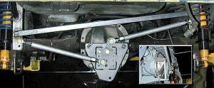
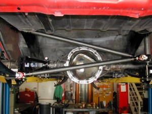
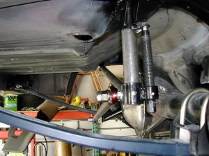
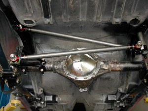
John found a place to mount the bar forward of the rear end, on the chassis. This required fabricating some custom mounts, welding them onto the car, and welding some mounts onto the axle. Letting the pictures talk-
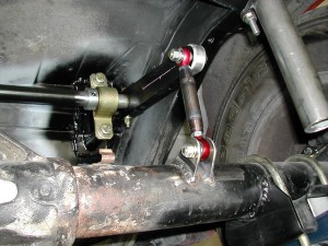
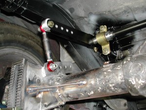
And the endlinks, adjustable on the driver side.
The bar itself is a 1″ center, the arms aluminum, and the bearings bronze, so it’s not too heavy. Lots of adjustment on driver side arm, and the ability to increase or decrease the adjustment range, with different center sections.
Panhard completion
One bummer thing is there really doesn’t seem to be anything out there for the car that’s good as is. Everything needs modification.
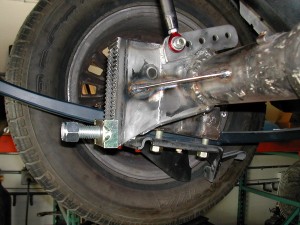
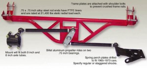
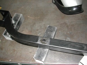
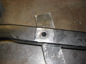
The panhard bar mounts from UB had a couple shortcomings. One, the axle-side mounts were really big and heavy, with all sorts of clamps and things. With it welded on, a lot less material is needed. So John hacked off a bunch of unnecessary material, and welded the puppy on there. Before:

After:
On the axle:
Those changes took a few pounds off the panhard parts, which means a few fewer pounds of unsprung weight. Another thing I see on so many of these cars is a truckload of parts bolted/welded to the rear axle (evil Steelitis rearing its ugly head again!). Sure, 5 new links and an 8 foot torque arm may control the axle well, but is it really worth another 75 pounds of unsprung weight to track over every bump?
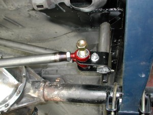
Another problem was the way the UB Machine chassis-side mount received the lateral loads from the panhard bar. Recall this pic from before:
The lateral compression/tension loads from the panhard aren’t in line with the vertical piece coming down from the chassis, or the cross brace. I was worried about the lateral loads causing the panhard mount piece to want to “twist” around the tubular down tube.
So out come the grinder and welder again, to modify that piece, to direct the loads into the chassis down tube, in the way I’d like to see.
This keeps the panhard in line with the support cross brace-
And in line with the support piece-
So now, the panhard rod is done. Swaybar in next post…
Front suspension continued
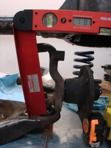
A while back I left off a post with this picture:
The angle, a bit over 8 degrees (90-81.7=8.3) is the “kingpin inclination” (KPI) or “steering axis inclination” (SAI) angle. It is basically, the angle from vertical about which the knuckle rotates when steered.
There are pros and cons to this angle being big or small. One pro, is it ends to reduce the “scrub radius” that some people say is a bad thing. It also provides a centering force akin to positive caster.
A con though, is that it produces positive camber in the outside wheel – i.e., if you turn right, the left front wheel will get positive camber just from turning. The higher the KPI, the more positive goes the camber. This is a Bad Thing.
Can’t change KPI in this class, really requires a whole new knuckle. But we can fight this Bad Thing with a Good Thing, and in our case that Good Thing is positive caster.
Caster is the same sort of angle as above, except as viewed from the side. Positive caster produces negative camber on the outside wheel when turned. The more positive the caster, the more negative camber gain.
Autocross has some fairly tight maneuvers, ones that often require large amounts of steering angle input. Long wheelbase cars like the Camaro have to use even more steering input around given radius corners (see CVD 4 – Skidpad for some explanation), making it all the more important that, to the maximum extent of our rules-bound ability, we minimize any unfavorable consequences of turning the wheel.
Many modern cars use a lot of caster. The Porsche 911 GT3 uses upwards of 8.5 degrees; some Mercedes-Benz come from the factory with over 11 degrees. Heck, even the latest Mustang uses 7 or more. Lots of sporty cars made in the last 20-30 years provide 5-7 degrees.
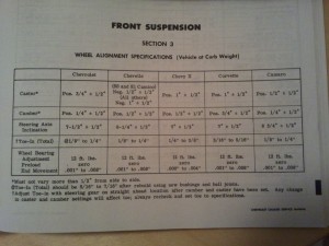
Most people don’t believe me when I tell them what the Camaro’s base caster setting is. Here’s photographic proof, from my Chevrolet Chassis Service Manual, (far right column):
That’s right, the factory caster setting is positive 1/2 degree, plus-or-minus 1/2 degree. Meaning potentially zero degrees positive caster! So with over 8 degrees of KPI/SAI, there is almost no positive caster to counteract that positive camber gain on the outside front tire.
Just another facet of how bad the first-gen Camaro’s front suspension is from the factory. 🙂
So, to try to nullify this Bad Thing we’ll add some positive caster to the equation. Common thinking amongst most of the first-gen Camaro guys is that “4 or 5 degrees is enough”…which of course means that I’ll be aiming for at least twice that much! 🙂 The thing is, even at about 8.5 degrees of positive caster, its beneficial effects are only canceling out the detrimental effects from the KPI. A first-gen Camaro with 12 degrees of positive caster will only see about the same positive effect from caster, that a “normal” car would get with 6-7 degrees.
Adding all this caster isn’t a trivial endeavor either. There’s a few side effects that must be managed.
One is an increase in steering effort. I’m a big believer in providing the driver with a stable, precise, sensitive, and consistent platform upon which to operate. If we require the driver to use big muscles to dance the car through the course, we can’t expect the driver to have a lot of precision touch in his inputs. To help enable this, I plan to run power steering. An excellent race seat will hold the driver in, without any stabilizing forces through the wheel. This should enable “fingertip” steering wheel forces, enabling the driver to maintain a much better feel for the front tires. I believe the power steering ratio on the Z28 was also a bit quicker, which I like – it’s also harder to be precise when you have to produce huge turns of the wheel in a small amount of time.
The other side effect is it can change your wheelbase. The traditional (and FSM-specified) way of adjusting camber and caster on these cars is to use shims on the upper control arm’s inner attachment point. Use of shims at both ends produces negative camber, and their use at one end or the other changes caster. The threaded upper bolts are long enough to produce large amounts of change. This method of caster adjustment moves the upper ball joint “back”, and if the hub is centered between the upper and lower ball joints, moves the wheel centerline back half that distance.
The problem here, is the whole wheel is moved back in the wheelwell, and with the amount of caster I plan to add, doing it all with the upper arm, would move the wheel back more than 1/2″. I want to be able to run very very low, and do everything I can to reduce or eliminate rubbing with the big 265-section front tire. The Camaro’s inner fender has the most vertical room right at the stock front wheel centerline, which means I need to keep the wheel centered to maximize how low I can go.
To keep the wheel centered, but still produce large caster values, means I need to also move the lower ball joint forward, while moving the upper ball joint rearward. If I move each equal amounts, the wheel stays centered in the wheelwell, and I get to enjoy the yummy KPI-canceling positive caster.
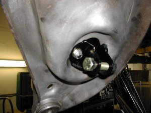
Since I’m spending my custom control arm allowance on replacement upper control arms, I have to stick with the stock lower arms. However, there is an allowance for replacement offset bushings. So long as these offset bushings don’t contain any more metal than stock, I can use them to produce some of this same caster gain. You can see in the pic below, how the mount axis goes through the bushing cylinders at an angle – this produces a clockwise rotation (in top view) of the driver’s side lower control arm, moving the lower ball joint forward.
John is just about completed with these custom Hydlar lower control arm offset bushings for the Camaro. There’s a good amount of “meat” to the stock bushings, allowing for a satisfying amount of longitudinal forward offset of the lower ball joint. It probably isn’t enough to produce entirely half of the caster I’m after, but it’ll be close, and should make a big difference in keeping the front wheels centered in the wheelwell.
A lot of the first-gen guys add a bunch of positive caster to their cars all with the upper arm, and run into bad rubbing problems, because of this rearward movement.
Anyway, these offset bushings are a relatively small detail. The thing many people overlook, is lots of small details start to add up. An ounce of weight savings here, a smidge of improved alignment there, maybe another 1/2 hp freed up, all make a difference. Those who remember their Calculus know, that even when you’re dealing with really really tiny quantities, so long as you find enough of them to add up, you can eventually end up with a substantial (Riemann ;)) sum.
This “sum of many tiny parts” thing was made most clear to me not in Calc class, but at the 2005 Solo National Championships, where I was codriving with Gary Thomason in his insane SM2 C5 Corvette. Anybody who knows Gary knows how meticulous he is in the care of his cars – not just their finish and appearance, but in their overall state of tune and function. Gary was constantly tweaking things with the car – 1/32″ rear toe changes between runs, fraction of a PSI difference in the tires, etc. I’ll never forget the morning of day 2, him looking to find a way to get the running lamps to stay off.
The car’s AFR-headed LS-based 408 was making 600+hp, but the real story was the insane low-end torque, combined with the stock short Z06 gearing. The thing would obliterate the tires with a hair’s too much throttle. It took a perfect alignment of the planets before you’d even consider full throttle, and on most courses you never got there. Yet here we were, out on the beat up old airbase at Forbes Field, trying to get the running lamps to stay off, which would reduce the load on the alternator and free up some tiny bit of HP.
We found a way to keep them off, and on his last run that day Gary blazed an unbelievably fast time to pull ahead of Andy McKee in his superior RX7, and take the championship. While obviously you need the Big Stuff like top driving skill and the right tires in place to be contending for a National Championship, I now know that what many perceived as alien ability, or good luck on an unusually fast run, was actually the synchronous coming together of an uncountable number of tiny, carefully orchestrated, details… including that ‘Vette’s last 1/3 of a horsepower.
Rear axle lateral locator complete
So you’d think with nearly complete freedom to design and implement a top-notch lateral locating device for this live axle car, one would choose a Watts link right? After all, a Watts offers perfect symmetry when turning left and right, and doesn’t move the axle laterally as the suspension moves through its range of travel.
Along those lines, the first big question for anybody implementing a Watts link, is whether to make the main pivot point chassis mounted, or axle mounted. Axle mounted (image courtesy Griggs Racing):
Chassis mounted (image courtesy Fays2):
There’s a couple imperfections with the Watts however. The first pertains to the above choice. If you choose the axle-mounted center pivot, then you get the “advantage” of a consistent roll center height. But half the world will tell you you’re an idiot, because the sprung mass of the car moves in squat and pitch, so the “lever arm” from the roll center to the center of gravity, changes during squat and pitch, dynamically altering the rear roll couple. Plus it’s harder to adjust.
So you can instead choose the chassis-mounted pivot. This keeps the roll couple more consistent as the car pitches and squats. But now you’ve got to build a big heavy structure to support the center pivot, plus…wait a second, maybe the roll couple changes from the diff-mounted center pivot (loose on entry, tight on exit) could be beneficial? By now the other half of the world thinks you’re an idiot for having done a chassis-mount Watts.
We won’t even talk about a Mumford link, which might be cool if you’re scratch designing a live-axle chassis, but on something like the Camaro it would take 40+lbs. of structure welded into the rear to support it.
In keeping with the style of a person building a 44 year old car for a Street Touring class, I’ve made the choice that lets everybody (not just half) think I’m an idiot – a panhard rod.
Now, we all know the downside of the panhard – it moves the axle laterally as the suspension moves. The shorter the panhard, the more movement. The panhard bar on the car now is about 34″ long, which is as long as it could be made when considering the packaging restraints of the leaf springs. Another mitigating factor is, as with the front, by keeping the rear suspension stiff, I’ll be able to minimize the vertical (and thus lateral) movement of the rear axle. At 2″ of travel (pretty much all it will get), the axle will shift laterally by only .06″, about 1/16″. This is not a completely negligible amount, but I plan to run tall-ish sidewall rear tires, which will mask much of this, and we see tires move around on their wheels by 1/2″ or more while under heavy load.
The other maligned characteristic of a panhard rods vs. Watts, is their asymmetry in handling. The roll center, usually defined as the bar’s midpoint, rises or falls based on which way you’re turning, and which way you have it mounted. This will always create a difference in the way the car behaves turning left vs. right. Even if you start with the bar horizontal at resting height, as the car rolls, the lateral forces fed through the now-non-horizontal bar will serve to load the rear axle differently depending on which way you turn.
On the surface this may seem like a bad thing, but it can be used to counteract other asymmetries. For instance, in a live axle rear car, on hard acceleration, driveshaft torque is going to tend to weight the driver’s rear tire, and unload the passenger rear tire – that’s why you always see drag racers mounting their battery in the right rear, and why live-axle cars usually have such a bad time putting down power out of right-hand turns. This car is going to be making good power with good gearing so when good grip is available, this asymmetrical loading can become very significant.
We can use the panhard to counteract this asymmetry somewhat, by mounting it to the left half of the axle, and to the chassis on the right. This puts the panhard in compression, when in a right-hand corner. That compression is going to help better load the rear axle in right-hand turns, counteracting some of the axle’s natural asymmetry.
And actually, there’s a lot that’s asymmetrical about any race track, and any Solo2 course – both are either clockwise or counter-clockwise (ProSolo, with its mirrored courses, is the exception). The panhard rod is unique in that it allows one to adjust-in some inherent asymmetry, that may help if a particular event features a strong abundance of key turns in one direction or the other. It’s also lighter and less complex than the other options.
My panhard bar is simple but should be very effective. The sawtooth axle-end adjuster and screw-type chassis-side adjuster supply an essentially infinite number of discrete adjustment postions, as opposed to the 4-5 “holes” most solutions offer.
The solution overall is only about 16 pounds, a good bit lighter than the Watts options I’ve seen out there. Only about 6 pounds of it is unsprung weight, and the axle-side mount (all unsprung) will be lightened a bit – it’s designed to be bolt-on to the axle, but by welding it on, can eliminate the weight of the bolts and some other unneeded structure, while actually making it stronger.
The rear suspension still isn’t done from a fabrication perspective, though it’s getting close. Where’s my rear sway bar? Still that to do, soon thereafter should see some progress on the front. There’s one or two goodies visible in the pics above, I’ll let people chew on them for a while before discussing them further…
Subframe connectors completed
Well these puppies are finally done! Not content with the method of attachment as provided, I had John modify them to add a third attachment point, about halfway down their length. John found a place that would work on the chassis, then drilled a hole and welded in a tube to hold the bolt:
Since the connectors don’t sit flush with the floor of the car at that point, he had to make custom delrin spacers between the car and the connector.
Here they are installed. They look like they’re different heights because they are. Uniformity of 60’s chassis aren’t quite what we see in more modern stuff-
My hope is this additional attachment point, on a different longitudunal axis (the as-delivered front and rear attachment points are in-line longitudinally) will provide a meaningful increase in torsional rigidity above-and-beyond the parts as they came. We can’t do weld in and are allowed 3 attachment points so by golly I’m going to make use of all three!
Every part on the car that doesn’t absolutely have to be there, is going to have to work hard to prove to me it’s worth its cost in pounds. I may do some testing down the road with the connectors removed, to see if, in measured time around a course, I’m getting 24 pounds’ worth of rigidity out of them. If their benefit is not worth their weight in time, off they go. These things are about as good as I think you could make 3-point bolted-in subframe connectors so if they aren’t worth it, nothing I do legally with the allowance would be.
Third attachment point comes through in proximity of rocker and pan reinforcement for seat mounts, should be a good spot to take some loads.
Front connections all snugged up
And the view from front to back.
Another benefit they should provide a good safe place to jack up the car from the side. The traditional front crossmember jack point will be inaccessible at the ride height I’m likely to end up with, especially since it looks now like we’ll be able to use factory-only spoilers – a rule change which happens to suit me PERFECTLY, as I’d only ever wanted to run the factory front air dam and rear lip spoiler. I don’t know if I’ll be able to use the traditional under-diff jack point in the rear either, once all the workings of the rear suspension are together. These things may end up providing the only good place to jack up the car. So hmmm, maybe I will have to keep them regardless…driving a car up ramps just to get a jack underneath is a tremendous pain – been there, done that.
CVD Series – Chapter 3 started
Made a couple updates to the CVD series, chapter 2 and 3a. If you mouse-over the ![]() box at top, it should provide a drop-down to all chapters.
box at top, it should provide a drop-down to all chapters.
Chapter 2 is a boring yet somewhat gruesome dissection of a classic autocross lap.
Chapter 3a is the longest yet, explaining the process for evaluating and comparing the rolling acceleration capability of two cars. This should be a good resource if you ever find yourself embroiled in a “horsepower vs. torque” debate.
Started work on 3b, then on to cornering! Car got back-burnered for a couple weeks while John works a little magic on an A-Mod autocross car.
